IEEEST
Standard IEEE power system stabilizer: notch filter of order up to four, two lead–lag blocks, washout, and output limiter.
Block Diagram
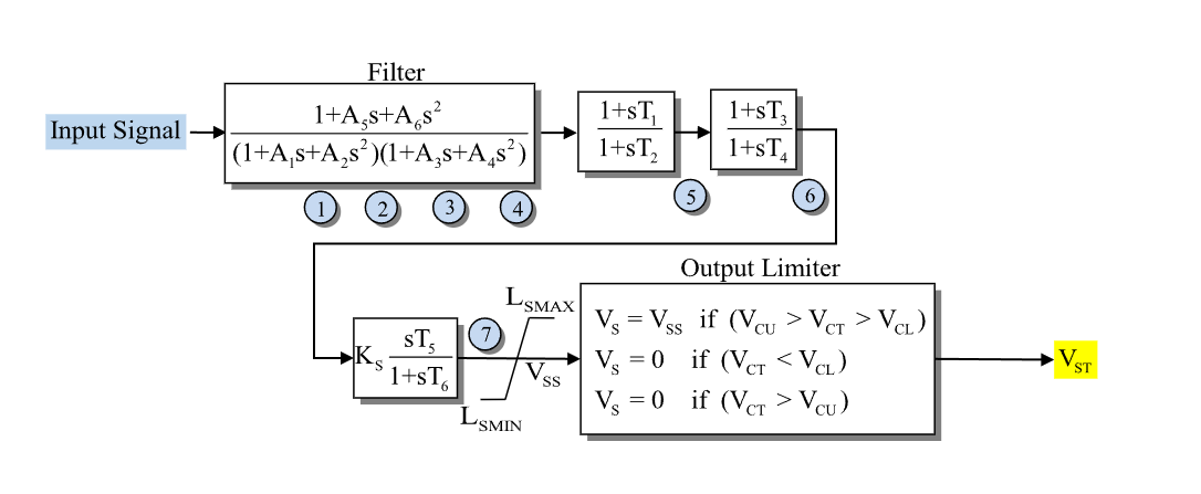
Figure 1: Stabilizer IEEEST model. Figure courtesy of PowerWorld
Model Parameters
Symbol |
Units |
JSON |
Description |
Typical Value |
Note |
|---|---|---|---|---|---|
\(A_1\) |
[s] |
|
Notch denominator coefficient |
1.013 |
|
\(A_2\) |
[s²] |
|
Notch denominator coefficient |
0.013 |
|
\(A_3\) |
[s] |
|
Notch denominator coefficient |
0.0 |
|
\(A_4\) |
[s²] |
|
Notch denominator coefficient |
0.0 |
|
\(A_5\) |
[s] |
|
Notch numerator coefficient |
1.013 |
|
\(A_6\) |
[s²] |
|
Notch numerator coefficient |
0.113 |
|
\(T_1\) |
[s] |
|
Lead–lag 1 numerator time constant |
0.0 |
|
\(T_2\) |
[s] |
|
Lead–lag 1 denominator time constant |
0.02 |
|
\(T_3\) |
[s] |
|
Lead–lag 2 numerator time constant |
0.0 |
|
\(T_4\) |
[s] |
|
Lead–lag 2 denominator time constant |
0.0 |
|
\(T_5\) |
[s] |
|
Washout numerator time constant |
1.65 |
|
\(T_6\) |
[s] |
|
Washout denominator time constant |
1.65 |
|
\(K_\mathrm{s}\) |
[p.u.] |
|
Stabilizer gain |
3.0 |
|
\(L_\mathrm{s}^{\min}\) |
[p.u.] |
|
Minimum stabilizer output limit |
-0.1 |
|
\(L_\mathrm{s}^{\max}\) |
[p.u.] |
|
Maximum stabilizer output limit |
0.1 |
The IEEE 421.5 IEEEST also defines a cutout window (\(V_\mathrm{cl}\), \(V_\mathrm{cu}\)) and an input delay (\(T_\mathrm{delay}\)). These parameters are accepted for input-format compatibility but are not modeled here.
Parameter Validation
A valid IEEEST parameter set must satisfy the following conditions:
Model Derived Parameters
The notch order is
Model Ports
Name |
Port |
Init |
Description |
|---|---|---|---|
|
Input |
Known |
Required stabilizer input signal |
|
Output |
Known |
Limited stabilizer output signal |
Model Variables
Internal Variables
Differential
Symbol |
Units |
Description |
Note |
|---|---|---|---|
\(x_1\) |
[p.u.] |
Notch filter state |
Held at zero when \(n=0\) |
\(x_2\) |
[p.u./s] |
Notch filter state |
Held at zero when \(n=0\) |
\(x_3\) |
[p.u./s²] |
Notch filter state |
Held at zero when \(n<3\) |
\(x_4\) |
[p.u./s³] |
Notch filter state |
Held at zero when \(n<4\) |
\(x_5\) |
[p.u.] |
Lead–lag 1 state |
Algebraic when \(T_2=0\) |
\(x_6\) |
[p.u.] |
Lead–lag 2 state |
Algebraic when \(T_4=0\) |
\(x_7\) |
[p.u.] |
Washout state |
Algebraic when \(T_6=0\) |
Algebraic
Symbol |
Units |
Description |
Note |
|---|---|---|---|
\(v_4\) |
[p.u.] |
Notch filter output |
|
\(v_5\) |
[p.u.] |
Lead–lag 1 output |
|
\(v_6\) |
[p.u.] |
Lead–lag 2 output |
|
\(v_7\) |
[p.u.] |
Unlimited stabilizer signal |
|
\(V_{\mathrm{ss}}\) |
[p.u.] |
Limited stabilizer signal (model output) |
External Variables
Differential
None.
Algebraic
Symbol |
Units |
Description |
Note |
|---|---|---|---|
\(u\) |
[p.u.] |
Stabilizer input signal |
Model Equations
Smooth functions: clamp.
Internal Equations
Differential
Algebraic
External Equations
None.
Initialization
The initial input determines the steady state; all derivatives initialize to zero.
Monitors
Monitor |
Units |
Description |
Note |
|---|---|---|---|
|
[p.u.] |
Limited stabilizer signal |
\(V_{\mathrm{ss}}\); model output |