LineDistributed
LineDistributed represents an \(N\)-phase, \(K\)-conductor distributed EMT line.
Block Diagram
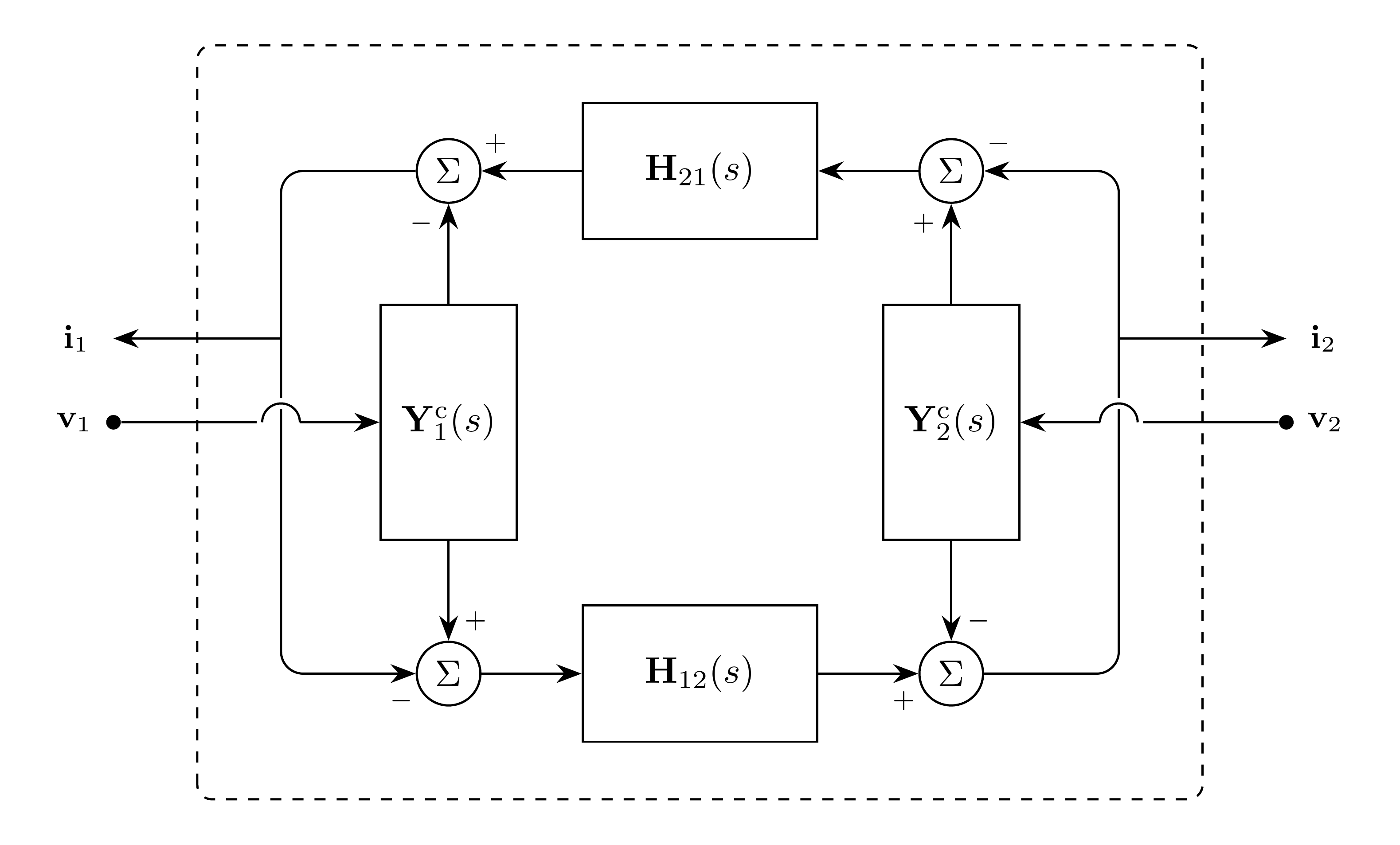
Figure 1: LineDistributed model
The conductor-to-phase mappings are shown in the equations and omitted from the diagram for clarity.
Model Parameters
Define the phase- and conductor-index sets
Symbol |
Units |
JSON |
Description |
Note |
|---|---|---|---|---|
\(N\) |
[-] |
|
Number of phases |
Required, positive integer |
\(K\) |
[-] |
|
Number of conductors |
Required, positive integer |
\(\mathbf{c}\) |
[-] |
|
Conductor phase-index list |
\(\mathbf{c} \in \mathcal{N}^K\) |
Parameter Validation
Model Derived Parameters
Model Ports
Symbol |
Port |
Type |
Units |
Description |
Note |
|---|---|---|---|---|---|
\(\mathbf{v}_1\) |
|
Input |
[V] |
Terminal 1 bus voltage |
\(\mathbf{v}_1 \in \mathbb{R}^N\) |
\(\mathbf{v}_2\) |
|
Input |
[V] |
Terminal 2 bus voltage |
\(\mathbf{v}_2 \in \mathbb{R}^N\) |
\(\mathbf{i}_1\) |
|
Output |
[A] |
Current injection at terminal 1 |
\(\mathbf{i}_1 \in \mathbb{R}^N\) |
\(\mathbf{i}_2\) |
|
Output |
[A] |
Current injection at terminal 2 |
\(\mathbf{i}_2 \in \mathbb{R}^N\) |
Submodels
Symbol |
Description |
Type |
Order |
JSON |
Inputs |
Outputs |
|---|---|---|---|---|---|---|
\(\mathbf{y}_1^\mathrm{c}\) |
Characteristic admittance at terminal 1 |
\(KQ_{\mathbf{y}^\mathrm{c}}\) |
|
\(\mathbb{R}^K\) |
\(\mathbb{R}^K\) |
|
\(\mathbf{y}_2^\mathrm{c}\) |
Characteristic admittance at terminal 2 |
\(KQ_{\mathbf{y}^\mathrm{c}}\) |
|
\(\mathbb{R}^K\) |
\(\mathbb{R}^K\) |
|
\(\mathbf{h}_{21}\) |
Propagation from terminal 2 to terminal 1 |
Composite |
|
\(\mathbb{R}^K\) |
\(\mathbb{R}^K\) |
|
\(\mathbf{h}_{12}\) |
Propagation from terminal 1 to terminal 2 |
Composite |
|
\(\mathbb{R}^K\) |
\(\mathbb{R}^K\) |
Yc and H each provide one coefficient set. The model assumes a reciprocal
uniform line, so
The two terminal-admittance instances maintain independent states, and the two directional propagation instances maintain independent states and histories.
Submodel Validation
The characteristic-admittance fits must be stable, proper, and positive real. Together with the propagation fits, they must produce a passive line model.
Submodel Wiring
Model Variables
Internal Variables
Differential
None.
Algebraic
Symbol |
Units |
Description |
Note |
|---|---|---|---|
\(\mathbf{i}_1^\mathrm{ref}\) |
[A] |
Reflected current at terminal 1 |
\(\mathbf{i}_1^\mathrm{ref} \in \mathbb{R}^K\) |
\(\mathbf{i}_2^\mathrm{ref}\) |
[A] |
Reflected current at terminal 2 |
\(\mathbf{i}_2^\mathrm{ref} \in \mathbb{R}^K\) |
External Variables
Differential
Symbol |
Units |
Description |
Note |
|---|---|---|---|
\(\mathbf{v}_1\) |
[V] |
Terminal 1 voltage owned by EMT bus |
\(\mathbf{v}_1 \in \mathbb{R}^N\) |
\(\mathbf{v}_2\) |
[V] |
Terminal 2 voltage owned by EMT bus |
\(\mathbf{v}_2 \in \mathbb{R}^N\) |
Algebraic
None.
Model Equations
Internal Equations
Differential
None.
Algebraic
External Equations
Initialization
Initialize the characteristic-admittance and propagation submodels.
Monitors
Monitor |
Units |
Description |
Note |
|---|---|---|---|
|
[A] |
Characteristic-admittance current at terminal 1 |
\(\mathbf{i}_1^\mathrm{c} \in \mathbb{R}^K\) |
|
[A] |
Characteristic-admittance current at terminal 2 |
\(\mathbf{i}_2^\mathrm{c} \in \mathbb{R}^K\) |
|
[A] |
Incident current at terminal 1 |
\(\mathbf{i}_1^\mathrm{inc} \in \mathbb{R}^K\) |
|
[A] |
Incident current at terminal 2 |
\(\mathbf{i}_2^\mathrm{inc} \in \mathbb{R}^K\) |