GASTPTI
GASTPTI is a gas turbine-governor model with speed-droop fuel control and an exhaust-temperature low-value selector.
Warning
GridKit does not yet apply the associated generator’s Governor Response Limits
modes Down Only and Fixed to GASTPTI. Normal response is always used.
Notes
PowerWorld caps its load reference at \(A_T\) during transient simulation; GridKit does not.
The GASTD-only
dbL/dbHspeed deadband is not part of GASTPTI.Unlike PowerWorld, GridKit rejects rather than swaps reversed \(V^{\min}\) and \(V^{\max}\) values.
Block Diagram
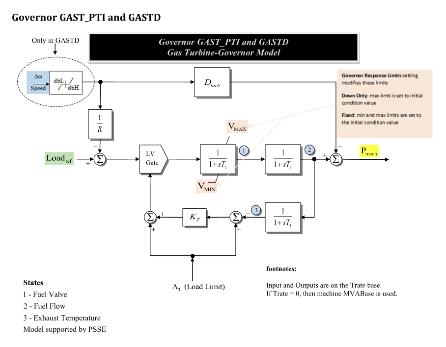
Figure 1: GASTPTI governor model. Figure courtesy of the PowerWorld GAST_PTI model reference.
Model Parameters
Symbol |
Units |
JSON |
Description |
Typical Value |
Note |
|---|---|---|---|---|---|
\(R\) |
[p.u.] |
|
Permanent speed droop |
0.05 |
Speed deviation per component-base power deviation |
\(T_1\) |
[s] |
|
Fuel-valve time constant |
0.4 |
|
\(T_2\) |
[s] |
|
Fuel-flow time constant |
0.1 |
|
\(T_3\) |
[s] |
|
Exhaust-temperature time constant |
3.0 |
|
\(A_T\) |
[p.u.] |
|
Ambient-temperature load limit |
1.0 |
Component base |
\(K_T\) |
[p.u.] |
|
Exhaust-temperature feedback gain |
2.0 |
|
\(V^{\max}\) |
[p.u.] |
|
Upper valve response limit |
1.0 |
Component base |
\(V^{\min}\) |
[p.u.] |
|
Lower valve response limit |
0.0 |
Component base |
\(D^\mathrm{turb}\) |
[p.u.] |
|
Turbine damping coefficient |
0.0 |
Component-base power per speed deviation |
\(T^\mathrm{rate}\) |
[MW] |
|
Turbine rating |
Required |
Same-valued MVA component base; GridKit addition |
Parameter Validation
A valid GASTPTI parameter set must satisfy the following conditions:
Model Derived Parameters
Let \(\epsilon_T=10^{-3}\ \mathrm{s}\). Accepted time constants below \(\epsilon_T\) are raised to that floor in place:
Multiplication by \(k_{\mathrm{base}}\) converts system-base power to component base. \(S^{\mathrm{sys}}\) and \(S^{\mathrm{base}}\) are stored in VA.
Model Ports
Name |
Port |
Init |
Description |
|---|---|---|---|
|
Input |
Known |
Optional machine speed deviation; defaults to zero |
|
Input |
Unknown |
Optional active-power/load reference; latches its initialized value when unattached |
|
Output |
Known |
Required mechanical power output |
Model Variables
Internal Variables
Differential
Symbol |
Units |
Description |
Note |
|---|---|---|---|
\(x_V\) |
[p.u.] |
Fuel-valve state |
State 1 in Fig. 1; component base |
\(x_F\) |
[p.u.] |
Fuel-flow state |
State 2 in Fig. 1; component base |
\(x_T\) |
[p.u.] |
Exhaust-temperature feedback state |
State 3 in Fig. 1; component base |
Algebraic
Symbol |
Units |
Description |
Note |
|---|---|---|---|
\(V_D\) |
[p.u.] |
Speed/load fuel demand |
Component base |
\(V_T\) |
[p.u.] |
Temperature-limit fuel demand |
Component base |
\(V\) |
[p.u.] |
Low-value selector output |
Component base |
\(P_\mathrm{m}\) |
[p.u.] |
Mechanical power output |
System base |
External Variables
Differential
None.
Algebraic
Symbol |
Units |
Description |
Note |
|---|---|---|---|
\(\omega\) |
[p.u.] |
Machine speed deviation |
Optional |
\(P^\mathrm{ref}\) |
[p.u.] |
Active-power/load reference |
Optional |
Model Equations
Smooth functions: antiwindup, min.
Internal Equations
Differential
The initialized constants \(V_{\mathrm{resp}}^{\min}\), \(V_{\mathrm{resp}}^{\max}\), and \(s^{\mathrm{valve}}\) are defined under Internal Initialization.
Algebraic
External Equations
None.
Initialization
Input Initialization
Internal Initialization
When \(s^{\mathrm{valve}}=1\), initialization requires a finite positive
\(m_T\) so iramp is defined. All candidates and response bounds are validated
before state, derivatives, or signals are changed; failed initialization is
atomic.
A response limit that excludes the initialized fuel flow is widened to include
it, and a warning is logged. This matches PowerWorld’s default
Modify Limits and Run treatment of initial limit violations.
Output Initialization
Initialization preserves the machine-seeded system-base \(P_\mathrm{m}\). An
attached pref signal receives the initialized reference; an unattached port
latches that value for subsequent residual evaluations.
Monitors
Monitor |
Units |
Description |
Note |
|---|---|---|---|
|
[p.u.] |
Mechanical-power output |
\(P_\mathrm{m}\); system base |
|
[p.u.] |
Fuel-valve state |
\(x_V\); component base |
|
[p.u.] |
Fuel-flow state |
\(x_F\); component base |
|
[p.u.] |
Exhaust-temperature feedback state |
\(x_T\); component base |
|
[p.u.] |
Speed/load fuel demand |
\(V_D\); component base |
|
[p.u.] |
Temperature-limit fuel demand |
\(V_T\); component base |
Appendix A: iramp
For a positive smooth-ramp output \(v>0\) and CommonMath smoothing parameter \(\mu\),
This is the positive-range inverse of GridKit’s smooth
ramp.