EXDC1
EXDC1 is a direct-current excitation-system model with a voltage transducer, input lead–lag compensation, a limited voltage regulator, exciter saturation, and stabilizing feedback.
Notes
Internal voltage signals are on component base.
The speed input is machine speed deviation, so the field-voltage multiplier is \(1 + \omega\).
Block Diagram
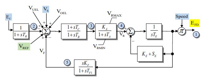
Figure 1: EXDC1 exciter model. Figure courtesy of the PowerWorld EXDC1 model reference.
Model Parameters
Symbol |
Units |
JSON |
Description |
Typical Value |
Note |
|---|---|---|---|---|---|
\(T_R\) |
[s] |
TBD |
Voltage transducer time constant |
0.0 |
|
\(K_A\) |
[p.u.] |
TBD |
Voltage-regulator gain |
40.0 |
|
\(T_A\) |
[s] |
TBD |
Voltage-regulator time constant |
0.1 |
|
\(T_B\) |
[s] |
TBD |
Input lead–lag denominator time constant |
0.0 |
|
\(T_C\) |
[s] |
TBD |
Input lead–lag numerator time constant |
0.0 |
|
\(V_R^{\max}\) |
[p.u.] |
TBD |
Maximum voltage-regulator output |
1.0 |
|
\(V_R^{\min}\) |
[p.u.] |
TBD |
Minimum voltage-regulator output |
-1.0 |
|
\(K_E\) |
[p.u.] |
TBD |
Exciter field resistance line slope margin |
0.1 |
|
\(T_E\) |
[s] |
TBD |
Exciter time constant |
0.5 |
|
\(K_F\) |
[p.u.] |
TBD |
Stabilizing feedback gain |
0.05 |
|
\(T_{F1}\) |
[s] |
TBD |
Stabilizing feedback time constant |
0.7 |
|
\(E_1\) |
[p.u.] |
TBD |
First saturation voltage point |
2.8 |
|
\(S_E(E_1)\) |
[p.u.] |
TBD |
Saturation coefficient at \(E_1\) |
0.08 |
|
\(E_2\) |
[p.u.] |
TBD |
Second saturation voltage point |
3.7 |
|
\(S_E(E_2)\) |
[p.u.] |
TBD |
Saturation coefficient at \(E_2\) |
0.33 |
JSON parameter names are not yet specified.
Parameter Validation
A valid EXDC1 parameter set must satisfy the following conditions:
All parameters must be finite.
The saturation points are either disabled together,
or define a valid two-point scaled-quadratic fit:
Model Derived Parameters
The scaled saturation contribution is
where \(q\) is the quadratic ramp. When saturation is disabled,
When one saturation value is zero,
When both saturation values are positive,
Model Ports
Name |
Port |
Init |
Description |
|---|---|---|---|
|
Input |
Known |
Compensated terminal-voltage magnitude |
|
Input |
Known |
Machine speed deviation |
|
Input |
Unknown |
Voltage-control reference |
|
Input |
Known |
Stabilizer input signal |
|
Input |
Known |
Under-excitation limiter input |
|
Input |
Known |
Over-excitation limiter input |
|
Output |
Known |
Field-voltage output |
Model Variables
Internal Variables
Differential
Symbol |
Units |
Description |
Note |
|---|---|---|---|
\(V_C\) |
[p.u.] |
Filtered terminal-voltage magnitude |
Algebraic when \(T_R = 0\) |
\(x_{\mathrm{LL}}\) |
[p.u.] |
Input lead–lag denominator state |
Algebraic when \(T_B = 0\) |
\(V_R\) |
[p.u.] |
Voltage-regulator output |
|
\(E_{\mathrm{fd}}'\) |
[p.u.] |
Field-voltage state |
Before the speed multiplier |
\(V_F\) |
[p.u.] |
Stabilizing feedback state |
Algebraic when \(T_{F1} = 0\) |
Algebraic
Symbol |
Units |
Description |
Note |
|---|---|---|---|
\(e_V\) |
[p.u.] |
Voltage-error summing output |
|
\(V_B\) |
[p.u.] |
Input lead–lag output |
|
\(s_e\) |
[p.u.] |
Scaled-quadratic saturation contribution |
|
\(V_{\mathrm{FE}}\) |
[p.u.] |
Exciter feedback drive |
|
\(E_{\mathrm{fd}}\) |
[p.u.] |
Field-voltage output |
External Variables
Differential
None.
Algebraic
Symbol |
Units |
Description |
Note |
|---|---|---|---|
\(E_C\) |
[p.u.] |
Compensated terminal-voltage magnitude |
|
\(\omega\) |
[p.u.] |
Machine speed deviation |
|
\(V_{\mathrm{ref}}\) |
[p.u.] |
Voltage-control reference |
|
\(V_S\) |
[p.u.] |
Stabilizer input signal |
|
\(V_{\mathrm{uel}}\) |
[p.u.] |
Under-excitation limiter input |
|
\(V_{\mathrm{oel}}\) |
[p.u.] |
Over-excitation limiter input |
Model Equations
Internal Equations
Differential
Algebraic
The limiter and saturation use the CommonMath antiwindup and quadratic ramp functions.
External Equations
None.
Initialization
Input Initialization
Internal Initialization
Initialization requires \(1 + \omega > 0\) and \(V_R^{\min} \le V_R \le V_R^{\max}\).
Output Initialization
Monitors
TBD.