IEEET1
IEEE Type 1 excitation-system model.
Warning
Compensation impedance is not modeled.
Notes
Voltage sensing uses the bus-voltage magnitude \(\sqrt{V_r^2 + V_i^2}\).
Block Diagram
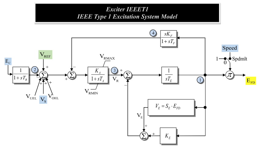
Figure 1: Exciter IEEET1 model. Figure courtesy of PowerWorld
Model Parameters
Symbol |
Units |
JSON |
Description |
Typical Value |
Note |
|---|---|---|---|---|---|
\(T_R\) |
[s] |
|
Time constant for voltage sensing |
0 |
|
\(K_A\) |
[p.u.] |
|
Coefficient for voltage regulation |
50 |
|
\(T_A\) |
[s] |
|
Time constant for voltage regulation |
0.04 |
|
\(K_E\) |
[p.u.] |
|
Exciter field resistance line slope margin; 0 requests automatic calculation, not a zero coefficient |
-0.06 |
|
\(T_E\) |
[s] |
|
Time constant for excitation system |
0.6 |
|
\(K_F\) |
[p.u.] |
|
Coefficient for feedback |
0.09 |
|
\(T_F\) |
[s] |
|
Time constant for feedback |
1.46 |
|
\(V_R^{\min}\) |
[p.u.] |
|
Lower limit to voltage regulation |
-1 |
|
\(V_R^{\max}\) |
[p.u.] |
|
Upper limit to voltage regulation |
1 |
|
\(E_1\) |
[p.u.] |
|
Saturation Parameter |
2.8 |
|
\(E_2\) |
[p.u.] |
|
Saturation Parameter |
3.73 |
|
\(S_1\) |
[p.u.] |
|
Saturation Parameter |
0.04 |
|
\(S_2\) |
[p.u.] |
|
Saturation Parameter |
0.33 |
|
\(I_{\mathrm{spdlim}}\) |
[binary] |
|
Speed limit flag indicator |
0 |
Parameter Validation
A valid IEEET1 parameter set must satisfy the following conditions:
Time constants below \(\epsilon_T\) are raised to \(\epsilon_T\) and logged as a warning; every other condition is a configuration error.
Model Derived Parameters
When saturation is disabled, \(S_A=0\) and \(S_B=0\). Otherwise, the parameters are chosen for the scaled-quadratic saturation model:
When exactly one saturation value is zero, the normal curve fit uses the corresponding voltage as the quadratic knee:
When both saturation values are positive, the non-extraneous solution is:
\(K_E\) is the configured exciter field resistance line slope margin. A nonzero configured value is used directly. The IEEE Std 421.5-2016 states:
In some programs, if \(K_E\) is entered as zero, \(K_E\) is automatically calculated by the program to represent a self-excited shunt field and a trimmed rheostat as its initial condition.
GridKit implements the PSS/E-compatible automatic-parameter rule, as specified in the PSS/E 33.4 Program Application Guide, Vol. II. The divisor \(10\) in \(V_R=V_R^{\max}/10=0.1V_R^{\max}\) is unitless and sets \(V_R\) to 10% of the maximum regulator output, retaining the per-unit units of \(V_R^{\max}\):
Model Ports
Name |
Port |
Init |
Description |
|---|---|---|---|
|
Bus |
Known |
Terminal bus voltage |
|
Input |
Known |
Machine speed deviation |
|
Input |
Unknown |
Voltage-control reference |
|
Input |
Known |
Stabilizer input signal |
|
Input |
Known |
Under-excitation limiter input |
|
Input |
Known |
Over-excitation limiter input |
|
Output |
Known |
Field-voltage output seeded by the machine |
Model Variables
Internal Variables
Differential
Symbol |
Units |
Description |
Note |
|---|---|---|---|
\(V_\mathrm{ts}\) |
[p.u.] |
Sensed terminal voltage |
|
\(V_R\) |
[p.u.] |
Voltage regulator |
|
\(E_{\mathrm{fd}}'\) |
[p.u.] |
Field voltage before the speed multiplier |
|
\(V_\mathrm{fx}\) |
[p.u.] |
Exciter feedback internal state |
Algebraic
Symbol |
Units |
Description |
Note |
|---|---|---|---|
\(V_{\mathrm{tr}}\) |
[p.u.] |
Terminal Voltage Error |
|
\(V_\mathrm{f}\) |
[p.u.] |
Feedback Voltage |
|
\(V_E\) |
[p.u.] |
Excitation control voltage |
|
\(E_{\mathrm{fd}}\) |
[p.u.] |
Field winding voltage |
|
\(k_\mathrm{sat}\) |
[p.u.] |
Scaled-quadratic saturation contribution |
\(E_{\mathrm{fd}}'S(E_{\mathrm{fd}}')\) |
External Variables
Differential
None.
Algebraic
Symbol |
Units |
Description |
Note |
|---|---|---|---|
\(V_r\) |
[p.u.] |
Real bus voltage component |
|
\(V_i\) |
[p.u.] |
Imaginary bus voltage component |
|
\(V_\mathrm{ref}\) |
[p.u.] |
Reference terminal voltage |
Signal port |
\(V_{\mathrm{uel}}\) |
[p.u.] |
Input from under excitation limiter |
Signal port |
\(V_{\mathrm{oel}}\) |
[p.u.] |
Input from over excitation limiter |
Signal port |
\(V_S\) |
[p.u.] |
Input from stabilizer controller |
Signal port |
\(\omega\) |
[p.u.] |
Machine speed deviation |
Signal port |
Model Equations
Smooth functions: antiwindup, \(q\).
Internal Equations
Differential
For readability, define the pre-limit derivative of \(V_R\) and voltage-sensing input:
The IEEET1 differential equations, as derived from the model diagram, are:
Algebraic
External Equations
None.
Initialization
The machine initializes \(E_{\mathrm{fd}}\) first. Set \(V_\mathrm{ref}\) to close the \(V_{\mathrm{tr}}\) equation:
All internal derivatives initialize to zero.
Monitors
Monitor |
Units |
Description |
Note |
|---|---|---|---|
|
[p.u.] |
Field winding voltage |
|
|
[p.u.] |
Scaled-quadratic saturation contribution |
\(S_B\,q(E_{\mathrm{fd}}'-S_A)\) |