SEXS-PTI
Simplified excitation-system model.
Block Diagram
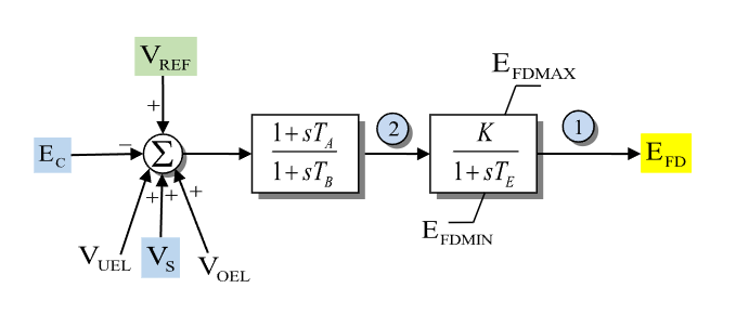
Figure 1: Exciter SEXS-PTI model. Figure courtesy of PowerWorld
Model Parameters
Symbol |
Units |
JSON |
Description |
Typical Value |
Note |
|---|---|---|---|---|---|
\(T_A\) |
[s] |
|
Numerator time constant of lead–lag block |
||
\(T_B\) |
[s] |
|
Denominator time constant of lead–lag block |
||
\(T_E\) |
[s] |
|
Exciter field time constant |
||
\(K\) |
[p.u.] |
|
Voltage regulator gain |
||
\(E_{\mathrm{fd}}^{\max}\) |
[p.u.] |
|
Maximum excitation output |
||
\(E_{\mathrm{fd}}^{\min}\) |
[p.u.] |
|
Minimum excitation output |
PowerWorld/PSS/E SEXS_PTI data often gives \(T_A/T_B\) as a ratio. GridKit stores \(T_A\) and \(T_B\) separately, so convert ratio-format data with \(T_A = (T_A/T_B)T_B\) before passing parameters to the model.
All six parameters are required; there are no defaults.
Parameter Validation
A valid SEXS-PTI parameter set must satisfy the following conditions:
Model Derived Parameters
None.
Model Ports
Name |
Port |
Init |
Description |
|---|---|---|---|
|
Bus |
Known |
Terminal bus voltage |
|
Input |
Unknown |
Voltage-control reference |
|
Input |
Known |
Stabilizer input signal |
|
Input |
Known |
Under-excitation limiter input |
|
Input |
Known |
Over-excitation limiter input |
|
Output |
Known |
Required field-voltage output seeded by the machine |
Model Variables
Internal Variables
Differential
Symbol |
Units |
Description |
Note |
|---|---|---|---|
\(V_R\) |
[p.u.] |
Lead–lag block state |
|
\(E_{\mathrm{fd}}\) |
[p.u.] |
Exciter field voltage output |
Algebraic
Symbol |
Units |
Description |
Note |
|---|---|---|---|
\(V_{\mathrm{tr}}\) |
[p.u.] |
Terminal voltage error signal |
External Variables
Differential
None.
Algebraic
Symbol |
Units |
Description |
Note |
|---|---|---|---|
\(V_r\) |
[p.u.] |
Terminal voltage, real component |
Bus input |
\(V_i\) |
[p.u.] |
Terminal voltage, imaginary component |
Bus input |
\(V_{\mathrm{ref}}\) |
[p.u.] |
Reference voltage |
Signal port |
\(V_S\) |
[p.u.] |
Stabilizer output |
Signal port |
\(V_{\mathrm{oel}}\) |
[p.u.] |
Over-excitation limiter signal |
Signal port |
\(V_{\mathrm{uel}}\) |
[p.u.] |
Under-excitation limiter signal |
Signal port |
Model Equations
Smooth functions: antiwindup.
Internal Equations
Differential
Algebraic
External Equations
None.
Initialization
The generator initializes the EFD signal first. SEXS-PTI then reads that value and any attached \(V_S\), \(V_{\mathrm{oel}}\), and \(V_{\mathrm{uel}}\) signals and assumes steady state:
All derivatives initialize to zero.
Monitors
Monitor |
Units |
Description |
Note |
|---|---|---|---|
|
[p.u.] |
Field-voltage output |
\(E_{\mathrm{fd}}\) |