Switch
Switch represents an ideal \(N\)-phase EMT switch between two buses. Series
current \(\mathbf{i}_{12}\) is directed from terminal 1 to terminal 2. The
required Boolean input open operates all phases: true is open and
false is closed. The switch contains no energy storage; switching
transients arise from the connected EMT network.
Block Diagram
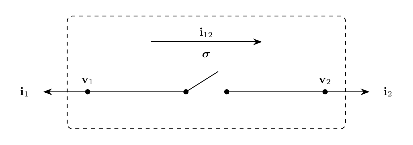
Figure 1: Switch model
Model Parameters
Symbol |
Units |
JSON |
Description |
Note |
|---|---|---|---|---|
\(N\) |
[-] |
|
Number of phases |
Required, positive integer |
Parameter Validation
Model Derived Parameters
None.
Model Ports
Symbol |
Port |
Type |
Units |
Description |
Note |
|---|---|---|---|---|---|
\(\mathbf{v}_1\) |
|
Input |
[V] |
Terminal 1 bus voltage |
\(\mathbf{v}_1 \in \mathbb{R}^N\) |
\(\mathbf{v}_2\) |
|
Input |
[V] |
Terminal 2 bus voltage |
\(\mathbf{v}_2 \in \mathbb{R}^N\) |
\(\mathrm{open}\) |
|
Input |
[-] |
Ganged switch command |
Required Boolean; |
\(\mathbf{i}_1\) |
|
Output |
[A] |
Current injection at terminal 1 |
\(\mathbf{i}_1 \in \mathbb{R}^N\) |
\(\mathbf{i}_2\) |
|
Output |
[A] |
Current injection at terminal 2 |
\(\mathbf{i}_2 \in \mathbb{R}^N\) |
Submodels
None.
Submodel Validation
None.
Submodel Wiring
None.
Model Variables
Internal Variables
Differential
None.
Algebraic
Symbol |
Units |
Description |
Note |
|---|---|---|---|
\(\mathbf{i}_{12}\) |
[A] |
Series current from terminal 1 to terminal 2 |
\(\mathbf{i}_{12} \in \mathbb{R}^N\) |
External Variables
Differential
Symbol |
Units |
Description |
Note |
|---|---|---|---|
\(\mathbf{v}_1\) |
[V] |
Terminal 1 voltage owned by EMT bus |
\(\mathbf{v}_1 \in \mathbb{R}^N\) |
\(\mathbf{v}_2\) |
[V] |
Terminal 2 voltage owned by EMT bus |
\(\mathbf{v}_2 \in \mathbb{R}^N\) |
Algebraic
None.
Model Equations
Internal Equations
Differential
None.
Algebraic
External Equations
Initialization
The open command is applied at \(t_0\) before enforcing the algebraic
equations. The switch has no additional model-specific initialization.
Monitors
Monitor |
Units |
Description |
Note |
|---|---|---|---|
|
[-] |
Switch command |
Boolean; |
|
[A] |
Series current from terminal 1 to terminal 2 |
\(\mathbf{i}_{12} \in \mathbb{R}^N\) |