ESDC1A
ESDC1A is an IEEE DC1A excitation-system model with a voltage transducer, input lead–lag compensation, a limited voltage regulator, exciter feedback and saturation, under-excitation limiter routing, and an optional speed multiplier.
Notes
Internal voltage signals are on component base.
The source diagram labels the optional multiplier input as
Speed; GridKit uses machine speed deviation, so the enabled multiplier is \(1+\omega\).The UEL selector routes \(V_{\mathrm{uel}}\) either through the high-value gate or through the voltage-error summing junction.
Block Diagram
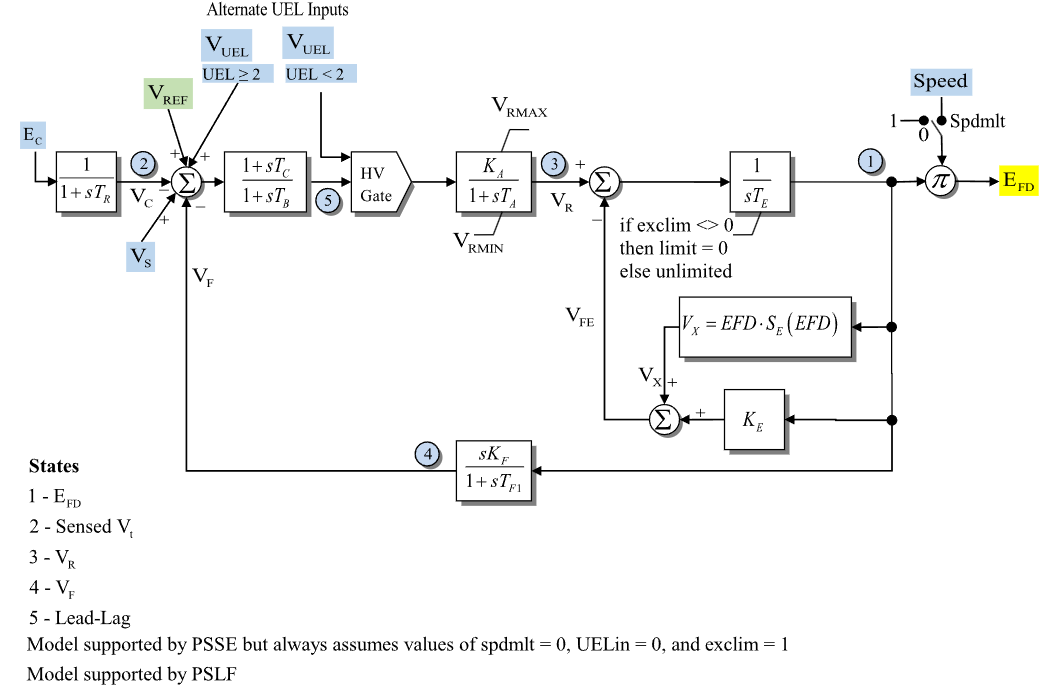
Figure 1: ESDC1A exciter model. Figure courtesy of the PowerWorld ESDC1A model reference.
Model Parameters
Symbol |
Units |
JSON |
Description |
Typical Value |
Note |
|---|---|---|---|---|---|
\(T_R\) |
[s] |
|
Voltage transducer time constant |
0.0 |
|
\(K_A\) |
[p.u.] |
|
Voltage-regulator gain |
40.0 |
|
\(T_A\) |
[s] |
|
Voltage-regulator time constant |
0.1 |
|
\(T_B\) |
[s] |
|
Input lead–lag denominator time constant |
0.0 |
|
\(T_C\) |
[s] |
|
Input lead–lag numerator time constant |
0.0 |
|
\(V_R^{\max}\) |
[p.u.] |
|
Maximum voltage-regulator output |
1.0 |
|
\(V_R^{\min}\) |
[p.u.] |
|
Minimum voltage-regulator output |
-1.0 |
|
\(K_E\) |
[p.u.] |
|
Exciter field resistance line slope margin; 0 requests automatic calculation, not a zero coefficient |
0.1 |
|
\(T_E\) |
[s] |
|
Exciter time constant |
0.5 |
|
\(K_F\) |
[p.u.] |
|
Stabilizing feedback gain |
0.05 |
|
\(T_{F1}\) |
[s] |
|
Stabilizing feedback time constant |
0.7 |
|
\(s_{\mathrm{spd}}\) |
[boolean] |
|
Field-voltage speed-multiplier flag |
|
|
\(E_1\) |
[p.u.] |
|
First saturation voltage point |
2.8 |
|
\(S_E(E_1)\) |
[p.u.] |
|
Saturation coefficient at \(E_1\) |
0.08 |
|
\(E_2\) |
[p.u.] |
|
Second saturation voltage point |
3.7 |
|
\(S_E(E_2)\) |
[p.u.] |
|
Saturation coefficient at \(E_2\) |
0.33 |
|
\(I_{\mathrm{uel}}\) |
[integer] |
|
Under-excitation limiter input-routing selector |
0 |
|
\(s_{\mathrm{lim}}\) |
[boolean] |
|
Exciter field-voltage-state lower-limit flag |
|
Every parameter is optional.
All real-valued parameters must be finite. Spdmlt and exclim must be
JSON booleans, and UEL must be a JSON integer.
Parameter Validation
A valid ESDC1A parameter set must satisfy the following conditions:
The saturation points are either disabled together,
or define a valid two-point scaled-quadratic fit:
Model Derived Parameters
Let \(\epsilon_T = 10^{-3}\ \mathrm{s}\). A time constant below \(\epsilon_T\) is raised to that floor in place, so every equation below uses the raised value:
When saturation is disabled, \(S_A = 0\) and \(S_B = 0\). Otherwise,
When one saturation value is zero,
and when both saturation values are positive,
\(K_E\) is the configured exciter field resistance line slope margin. A nonzero configured value is used directly. The IEEE Std 421.5-2016 states:
In some programs, if \(K_E\) is entered as zero, \(K_E\) is automatically calculated by the program to represent a self-excited shunt field and a trimmed rheostat as its initial condition.
GridKit implements the PSS/E-compatible automatic-parameter rule, as specified in the PSS/E 33.4 Program Application Guide, Vol. II. The divisor \(10\) in \(V_R=V_R^{\max}/10=0.1V_R^{\max}\) is unitless and sets \(V_R\) to 10% of the maximum regulator output, retaining the per-unit units of \(V_R^{\max}\):
Model Ports
Name |
Port |
Init |
Description |
|---|---|---|---|
|
Bus |
Known |
Terminal bus voltage |
|
Input |
Known |
Machine speed deviation |
|
Input |
Unknown |
Voltage-control reference |
|
Input |
Known |
Stabilizer input signal |
|
Input |
Known |
Under-excitation limiter input |
|
Output |
Known |
Field-voltage output |
Known values are seeded before initialization and preserved. Unknown inputs
are initialized in attached signal storage or held constant when unattached. The
efd output must be assigned. The speed input is required when
\(s_{\mathrm{spd}} = 1\); every other signal input is optional. Unattached speed,
vs, and vuel inputs default to zero.
Model Variables
Internal Variables
Differential
Symbol |
Units |
Description |
Note |
|---|---|---|---|
\(E_{\mathrm{fd}}'\) |
[p.u.] |
Exciter field-voltage state |
State 1 in Fig. 1; lower bounded at zero when \(s_{\mathrm{lim}} = 1\); before the optional speed multiplier |
\(V_C\) |
[p.u.] |
Filtered terminal-voltage magnitude |
State 2 in Fig. 1 |
\(V_R\) |
[p.u.] |
Voltage-regulator output |
State 3 in Fig. 1 |
\(V_F\) |
[p.u.] |
Stabilizing feedback state |
State 4 in Fig. 1 |
\(x_{\mathrm{LL}}\) |
[p.u.] |
Input lead–lag denominator state |
State 5 in Fig. 1 |
Algebraic
Symbol |
Units |
Description |
Note |
|---|---|---|---|
\(e_V\) |
[p.u.] |
Voltage-error summing output |
|
\(V_{\mathrm{LL}}\) |
[p.u.] |
Input lead–lag output |
|
\(V_{\mathrm{HV}}\) |
[p.u.] |
High-value gate output |
|
\(s_e\) |
[p.u.] |
Scaled-quadratic saturation contribution |
\(E_{\mathrm{fd}}'S_E(E_{\mathrm{fd}}')\) |
\(V_{\mathrm{FE}}\) |
[p.u.] |
Exciter feedback drive |
|
\(E_{\mathrm{fd}}\) |
[p.u.] |
Field-voltage output |
Published through |
External Variables
Differential
None.
Algebraic
Symbol |
Units |
Description |
Note |
|---|---|---|---|
\(V_r\) |
[p.u.] |
Terminal voltage, real component |
Bus input |
\(V_i\) |
[p.u.] |
Terminal voltage, imaginary component |
Bus input |
\(\omega\) |
[p.u.] |
Machine speed deviation |
Signal port |
\(V_{\mathrm{ref}}\) |
[p.u.] |
Voltage-control reference |
Signal port |
\(V_S\) |
[p.u.] |
Stabilizer input signal |
Signal port |
\(V_{\mathrm{uel}}\) |
[p.u.] |
Under-excitation limiter input |
Signal port |
Model Equations
Smooth functions: antiwindup, max, \(q\), \(\rho\).
Internal Equations
Differential
Define the pre-limit exciter field-voltage rate:
The field-voltage-state limiter uses the fixed-lower-bound anti-windup rule of Appendix A.
Algebraic
External Equations
None.
Initialization
Input Initialization
Initialization never replaces the seeded value held in \(E_{\mathrm{fd}}\).
Internal Initialization
All internal derivatives initialize to zero. The UEL high-value gate uses the inverse smooth ramp \(\rho^{-1}\):
Initialization rejects a non-finite or zero bus-voltage magnitude, a non-finite field-voltage seed, non-finite Known signal inputs, a nonpositive speed multiplier \(1 + s_{\mathrm{spd}}\omega\), \(E_{\mathrm{fd}}'<0\) while \(s_{\mathrm{lim}}=1\), initial \(V_R\) outside \([V_R^{\min},V_R^{\max}]\), and high-value-gate active starts with \(s_{\mathrm{uel}} = 0\) and \(V_{\mathrm{HV}}\le V_{\mathrm{uel}}\).
A rejected initialization leaves states and signals unchanged.
Output Initialization
ESDC1A writes the resolved voltage-control reference to an attached vref
signal input. If no controller is connected, that value is used as a constant
reference input.
Monitors
Monitor |
Units |
Description |
Note |
|---|---|---|---|
|
[p.u.] |
Field-voltage output |
\(E_{\mathrm{fd}}\) |
|
[p.u.] |
Filtered terminal-voltage magnitude |
\(V_C\) |
|
[p.u.] |
Voltage-regulator output |
\(V_R\) |
|
[p.u.] |
Stabilizing feedback state |
\(V_F\) |
|
[p.u.] |
Scaled-quadratic saturation contribution |
\(s_e\) |
|
[p.u.] |
Exciter feedback drive |
\(V_{\mathrm{FE}}\) |
Appendix A: awmin
The exact anti-windup rule at a fixed lower bound \(\ell\) is
The model evaluates this rule with the following smooth approximation:
CommonMath defines the above
and sigmoid targets and smooth
approximations.